This Cosmic Ray (Muon) Detector Kit is an open-source hardware project that has come about as a result of tinkering and building many Cosmic Ray detectors of various types since 2007. I’m regularly approached by people wanting me to construct them or needing assistance. These include musicians, artists, educators, and enthusiasts. However, juggling new projects with job and family life have posed some constraints. Consequently, I’ve recognised the need to develop a straightforward simplified kit that will empower anyone to construct and customise their own detector. For whatever their intentions or interest: education, for art, music or just wacky nonsense. My reasons are: I have a love for making things and a passion for science.

Please note: Geiger–Müller tubes use high-voltage DC between 350 and 900V, depending on the manufacturer. Please be aware that building and using such equipment comes with a risk of potential shock. It is only recommended for construction or use by individuals with experience.

The design of this kit is based around two Geiger–Müller tubes. A technology that has been embraced by many astrophysicists and educators since the early 20th century when Cosmic Rays were initially identified. Despite the evolution of alternative detection methods involving photomultipliers or SiPM coupled with a scintillator. A Geiger–Müller tube in my opinion currently persists as the most economical and accessible technology for Do-It-Yourself (DiY) detector projects.
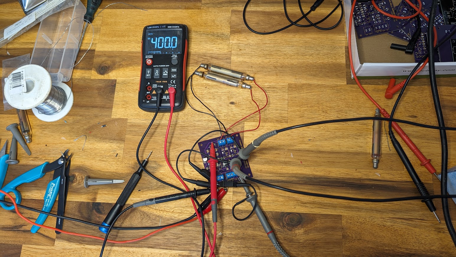
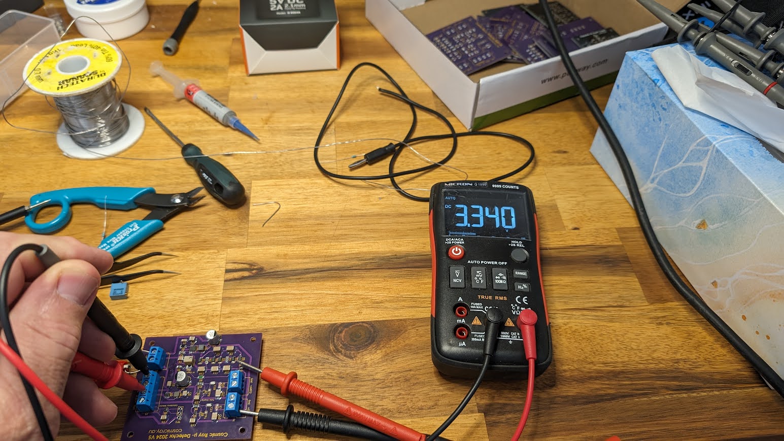
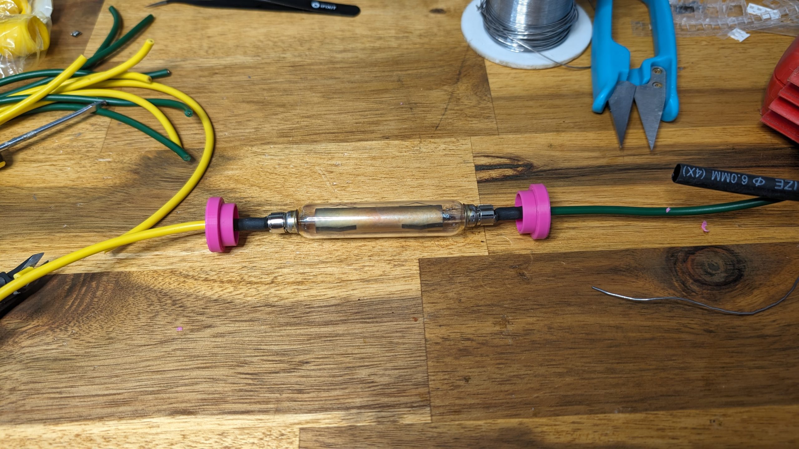
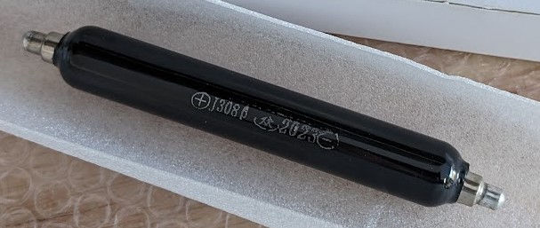
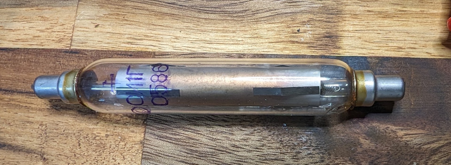
A Geiger–Müller tube (GMT) typically functions at a high voltage around 400V DC or even higher, depending on the manufacturer. There are many low-cost versions available, such as surplus ex-Soviet models (as below) and other more modern manufacturers, most of which operate within the range of 350 to 450V. Despite this elevated voltage, these tubes consume very little power, operating in the microamp region since they operate in series with a high-value resistor typically around 10 Megaohms.

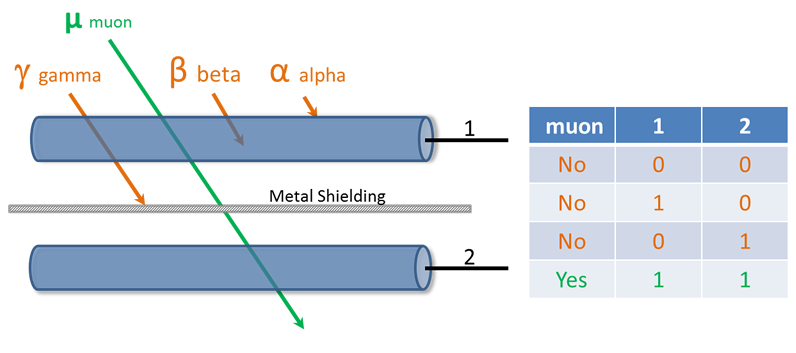
The bare minimum requirement for any cosmic ray muon detector involves at least two GMT tubes enclosed inside a non-ferrous metal shielding and a coincidence circuit. This will effectively filter out any low-energy terrestrial background radiation from Cosmic Ray initiated muons.
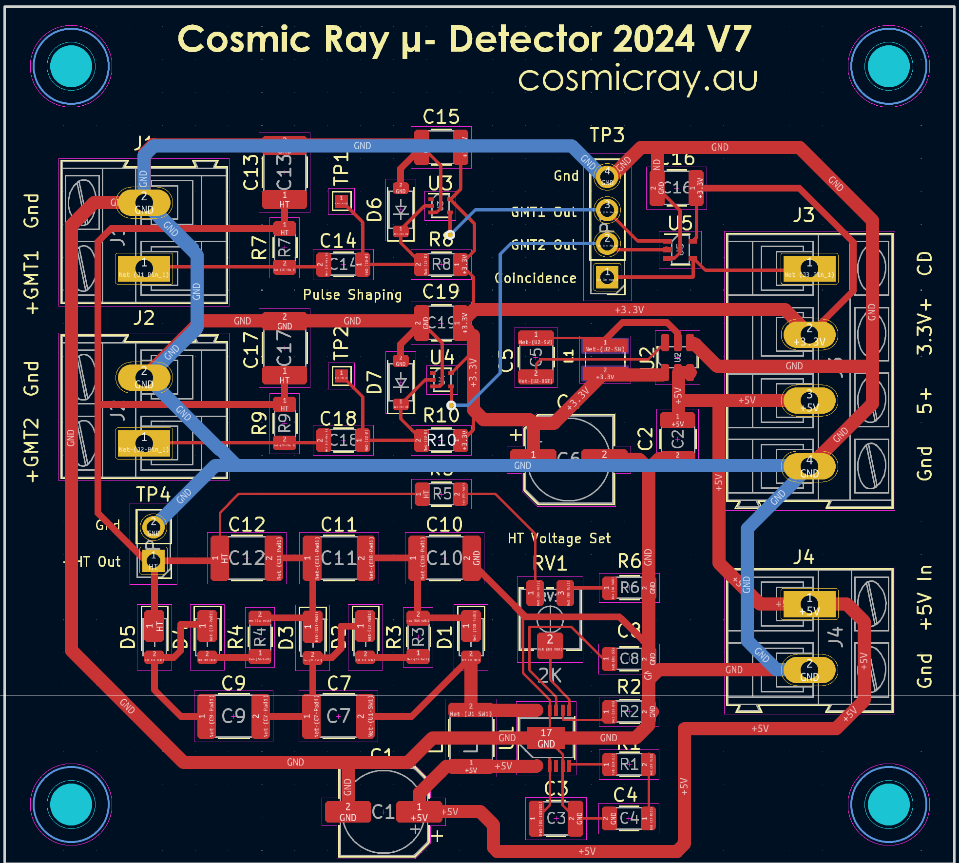
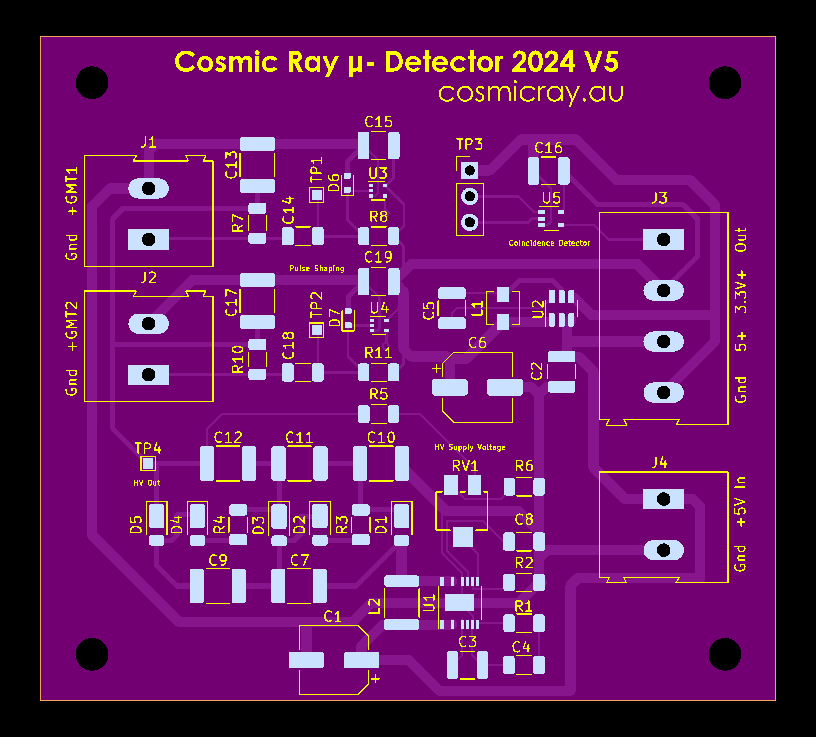
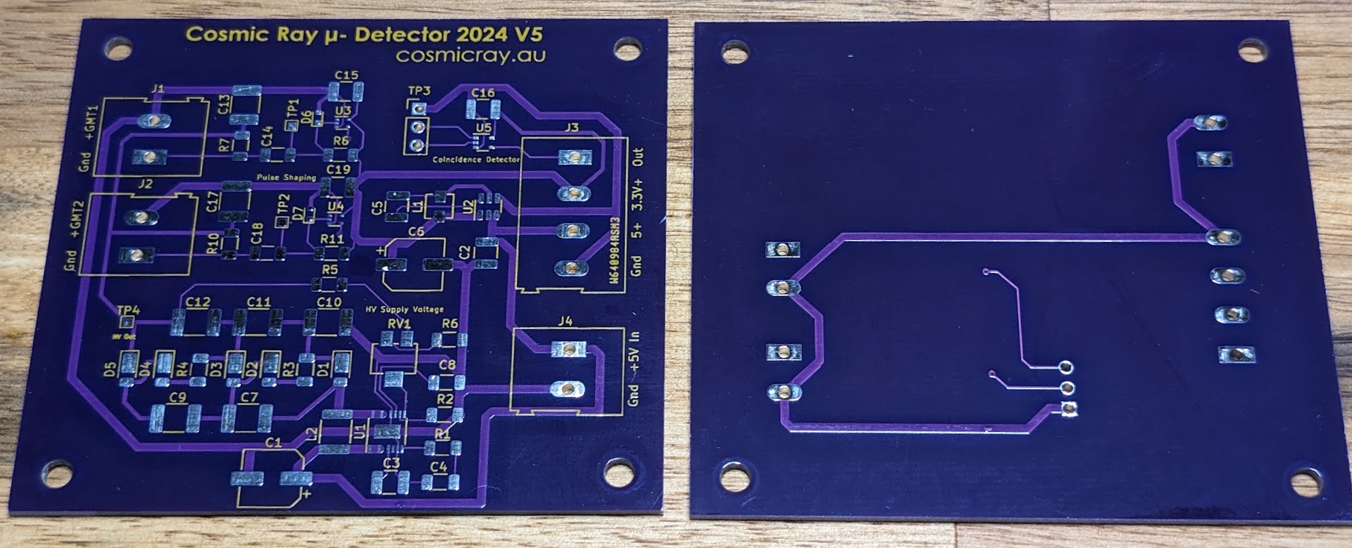
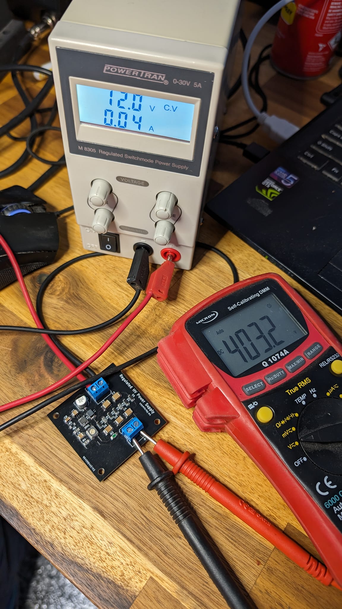
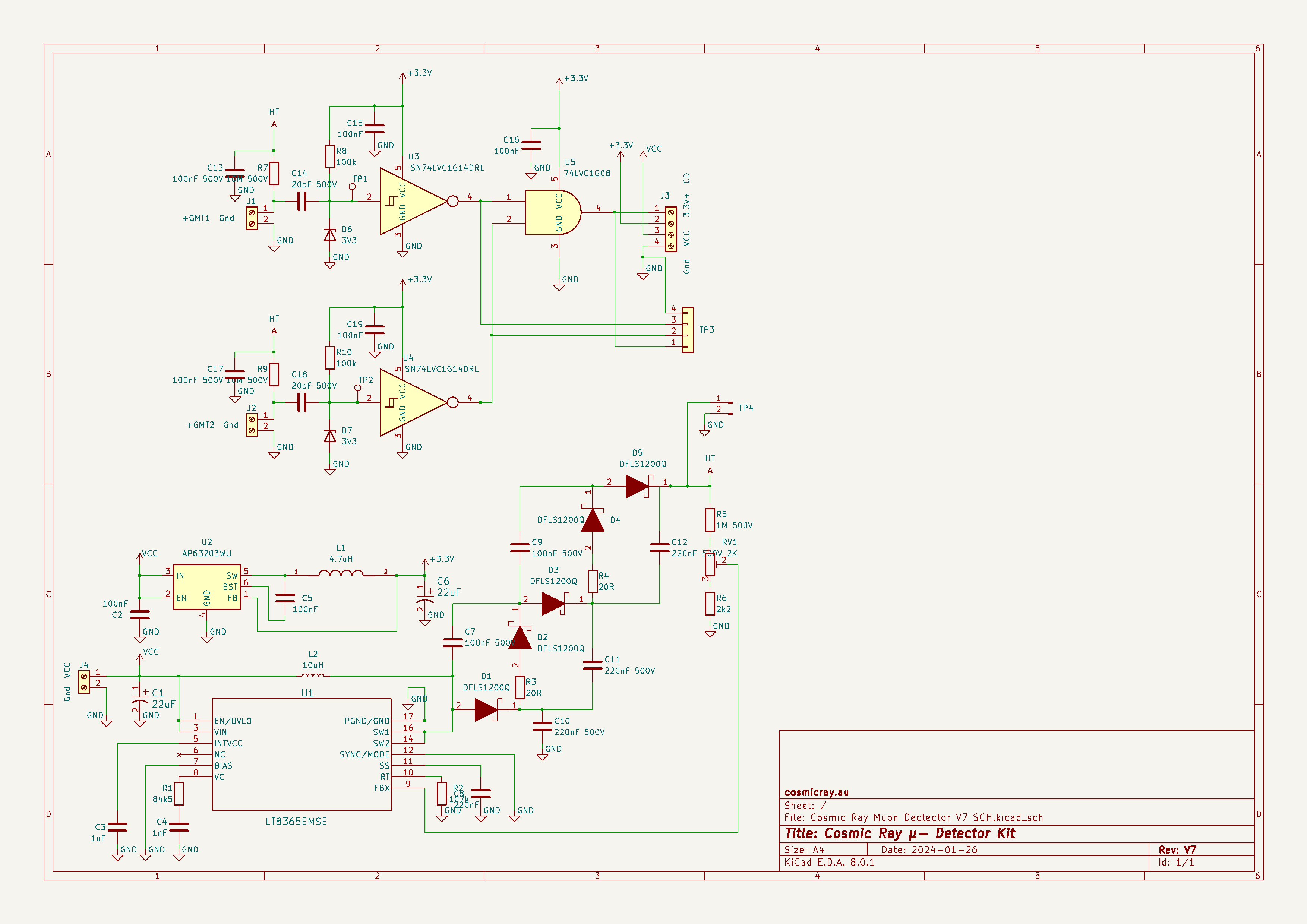
The output impedance of a basic GMT circuit is very high and so is also susceptible to noise, RFI and static discharge. Therefore it is crucial to use in combination with a low-noise regulated power supply to ensure reliability when using multiple GMTs. To meet this requirement, I have designed a power supply using the Analog Devices LT8365 Low IQ Boost Converter and voltage multiplier with an adjustable feedback circuit. This allows the HT voltage to be set at a level that multiple GMT can be trigger consistently and also provides compatibility with various GMT manufacturer voltages, enhancing the flexibility and adaptability of the design.
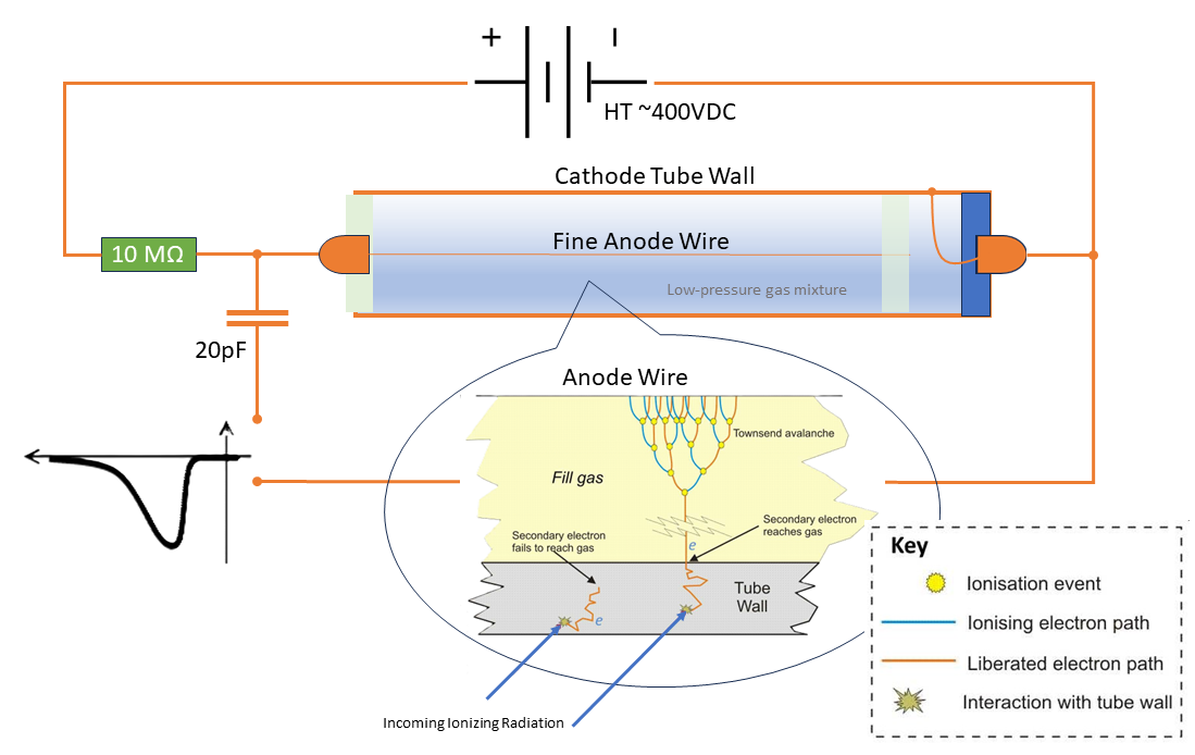
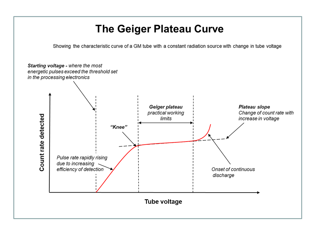
Setting the correct voltage is crucial when operating the Geiger–Müller Tube (GMT). When an ionizing particle passes through the GMT, it ionizes the gas inside, causing the resistance between the Anode and Cathode to decrease rapidly before returning to its initial state. This phenomenon occurs within a specific voltage range. If the voltage is too low, ionization will not occur; conversely, if the voltage is too high, the ionization may not be properly quenched, potentially damaging the tube and compromising accuracy. Therefore, maintaining the appropriate regulated voltage is essential for ensuring optimal performance and accuracy when used with multiple GMT.

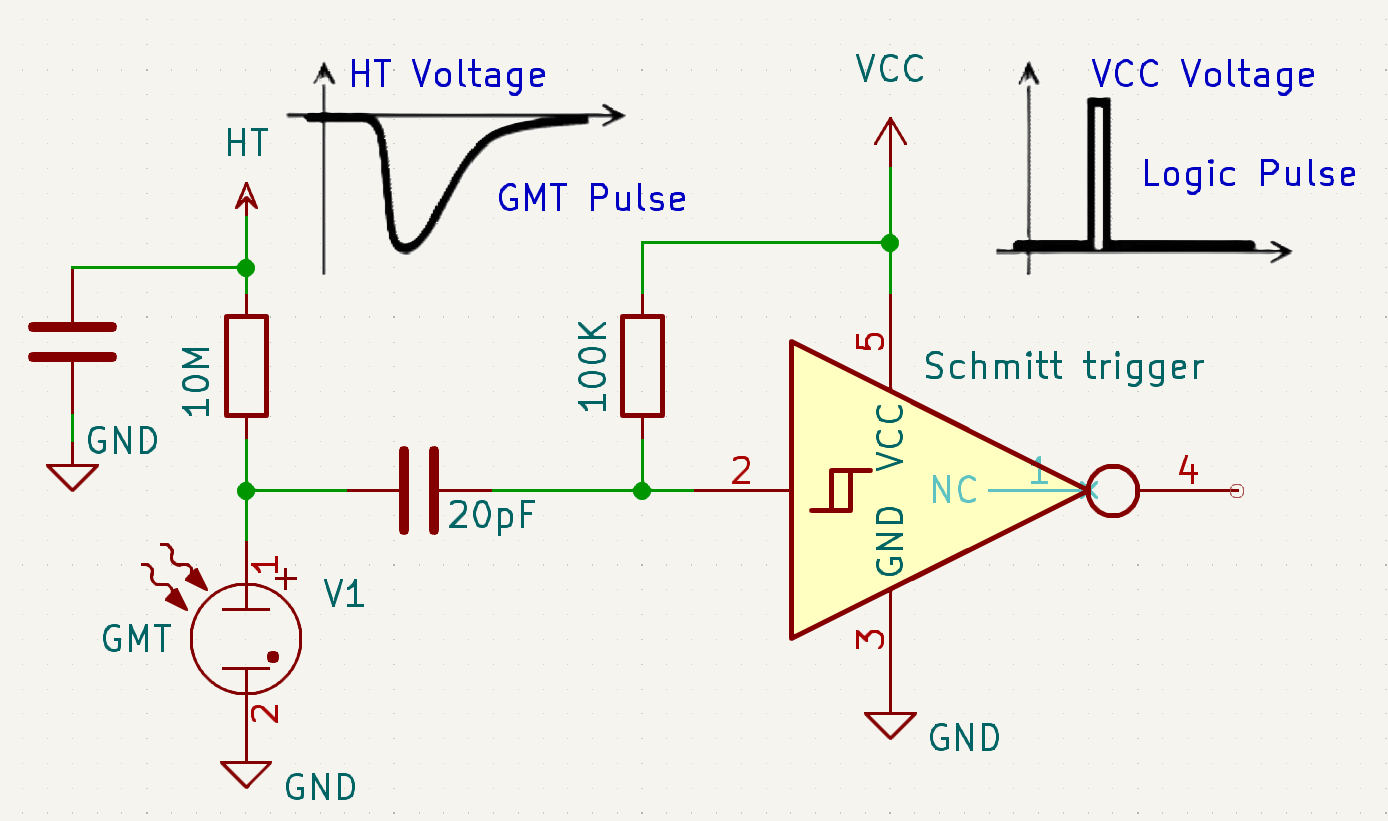
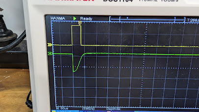
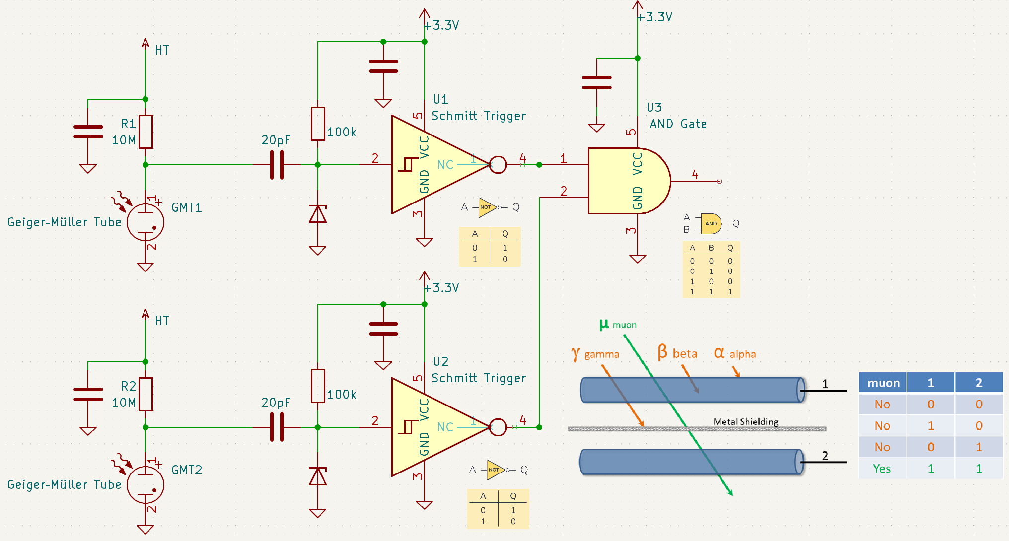
Another critical aspect of a detector circuit involves the conversion of the pulse generated by a Geiger–Müller tube (GMT) down to a usable level used by the logic circuit. At the juncture where the high-value resistor ~10M and GMT connect in series, a voltage drop will occur with regards to ground. At this point a low-value capacitor ~20pF is coupled to the input of an Inverting Schmitt Trigger which has been bias High (1) with another high value resistor ~100K at the logic circuits supply voltage +3.3V meaning the output of the Schmitt Trigger will be Low (0). When the negative pulse of the GMT is seen by the Schmitt Trigger it will register as Low (0) and and the output will be High (1), for the duration negative traveling transition.
Another aspect of the a cosmic ray detector measuring a coincidence of pulses from the two GMT. Now that we have logic level pulses it is a simple matter of using an AND Gate.
Named a “coincidence circuit” this invention emerged in the 1930s, courtesy of Bruno Rossi, an Italian experimental physicist captivated by the mysteries of Cosmic Rays. Motivated by a desire for a more practical and dependable method of measuring these phenomena, Although this idea may seem simple Rossi’s invention marked a significant advancement and not just in cosmic ray detection.

The main concept behind a ‘coincidence circuit‘ in signal processing is that if a detector identifies a signal pulse amidst the random noise pulses inherent in the detector and environment, there is a certain probability that the detected pulse is actually a noise pulse. However, if two detectors simultaneously detect the same signal pulse, the probability that it is a noise pulse in both detectors is statistically squared. The rate of background radiation in most locations is very low, only a few counts per minute, but with the addition of shielding, this rate is further reduced. Consequently, the likelihood of coincidence detection being cosmic ray muons rather than background radiation is significantly increased.
Shielding in a Cosmic Ray Muon Detector
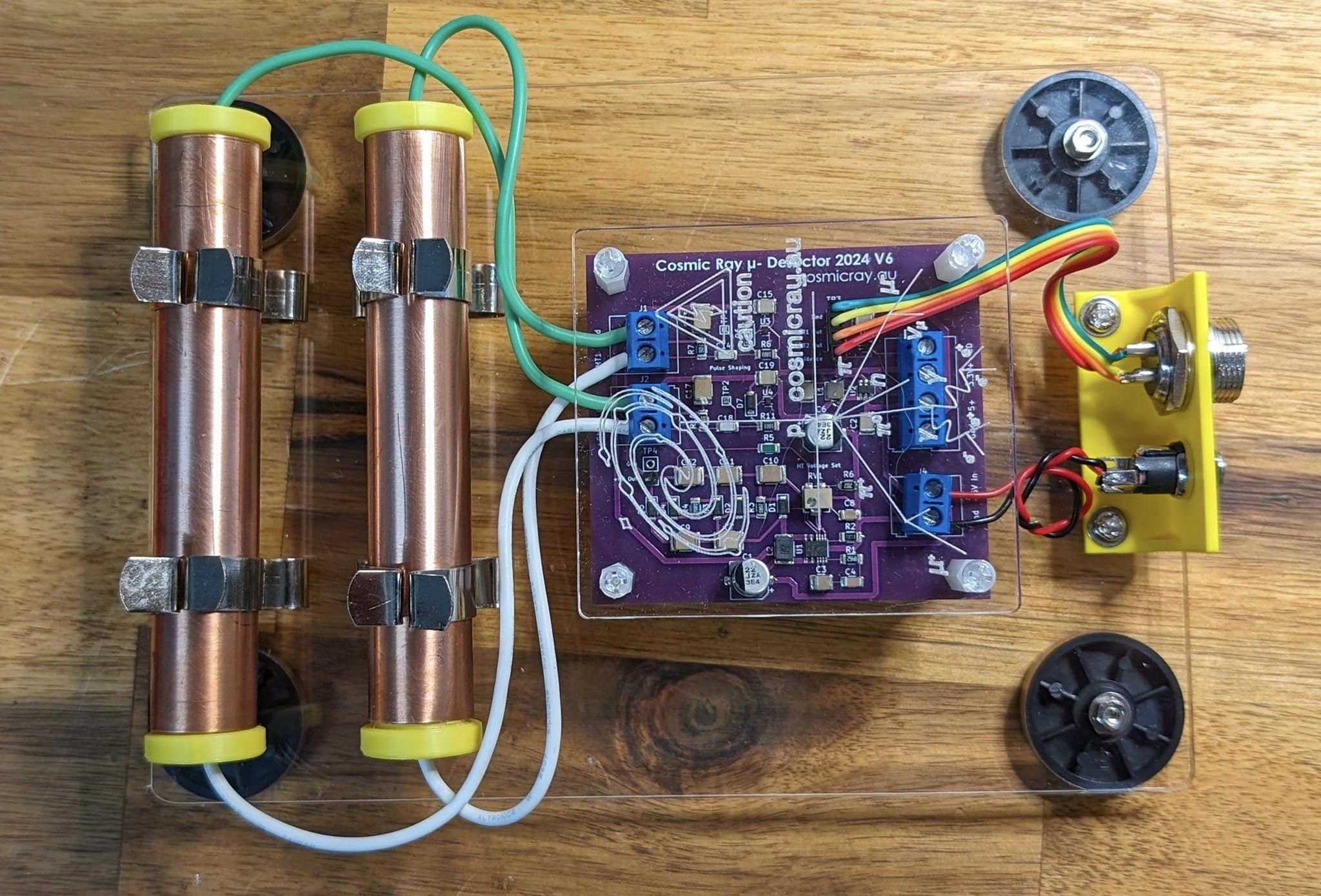
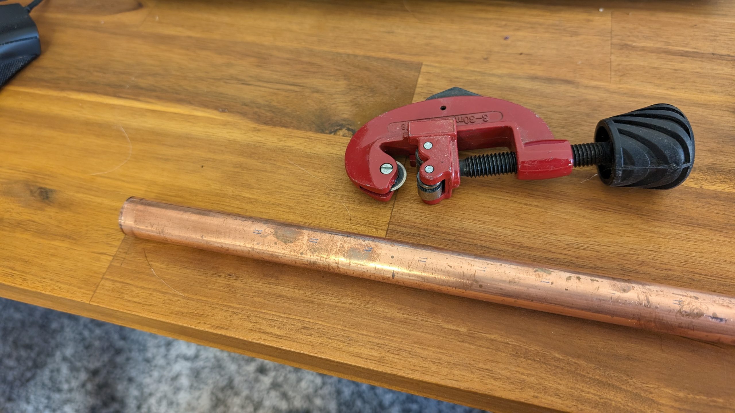
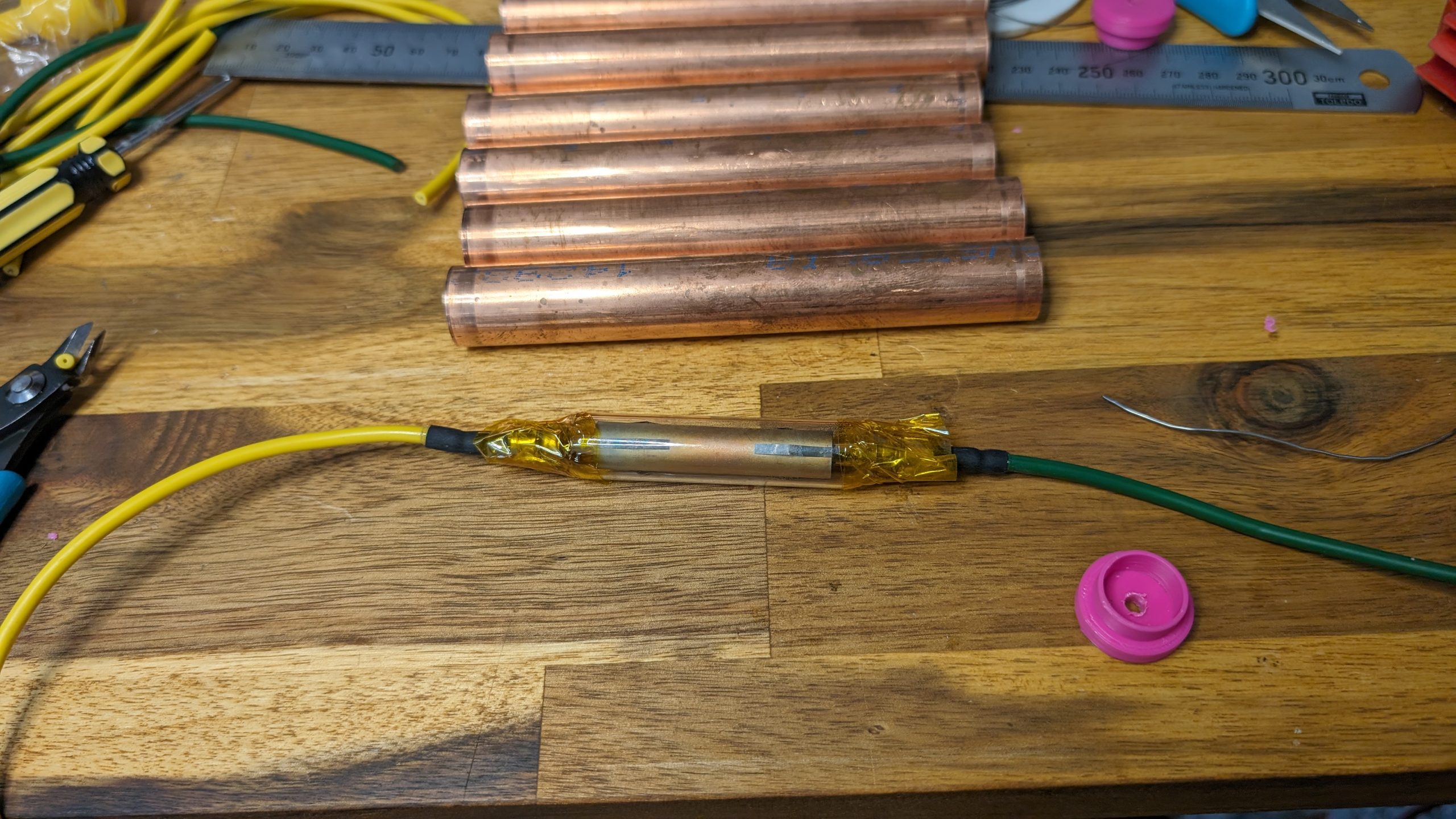
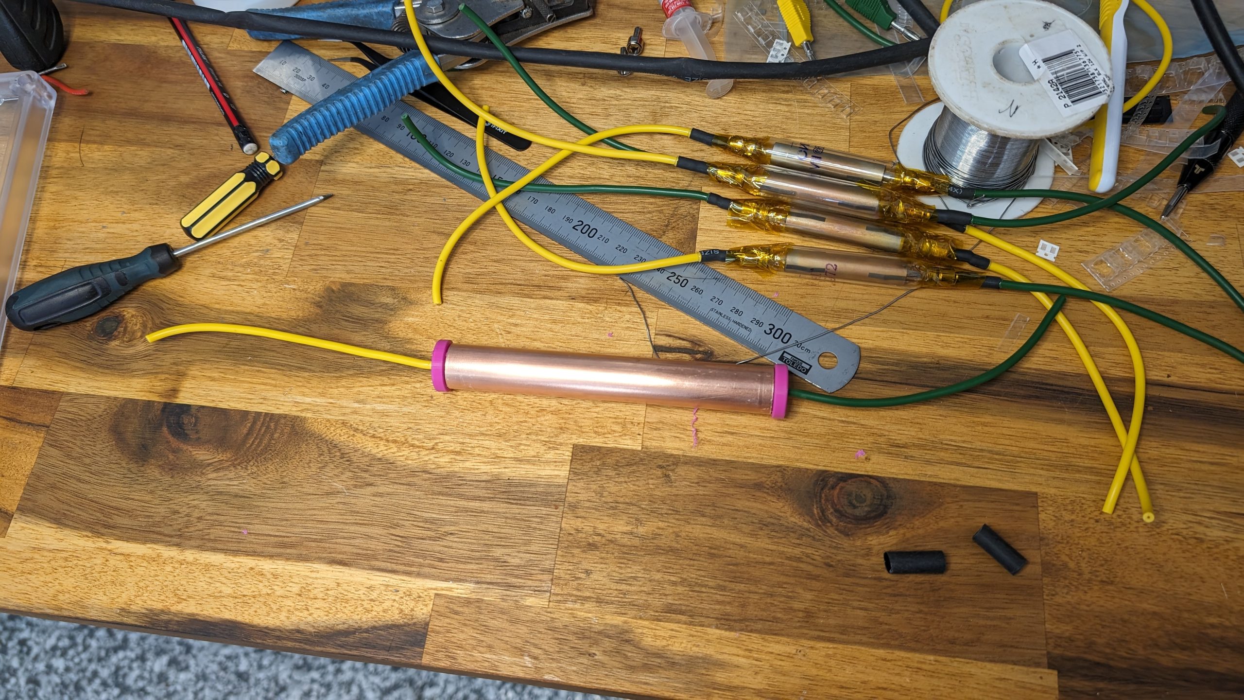
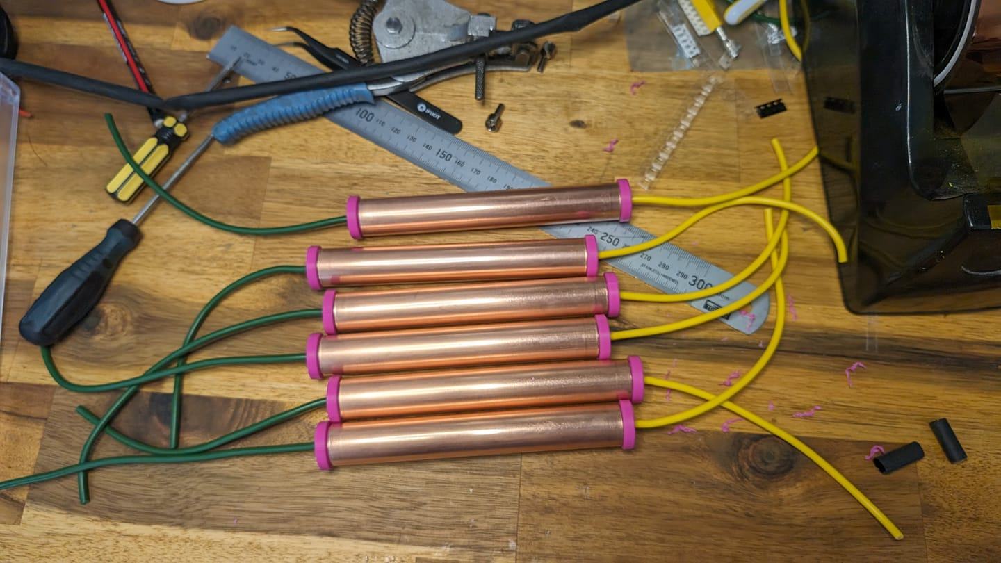
Use non-ferrous, non-magnetic metals to avoid the potential of deflecting charged particals. Lead, Aluminum, or Copper being viable options. Copper, in particular, is a favorable choice due to its ease of workability, readily available in many tube diameters, electrical conductivity reducing radio frequency interference (RFI), and lower toxicity than lead.

Shielding is mainly used to increase the statistical difference of noise in the coincidence circuit. With 2 main aims: 1) To differentiate the noise within each Geiger–Müller tube due to natural radioactive decay in matter e.g. gasses, glass and metals surrounding the detector and materials used to manufacture Geiger–Müller tube. 2) Cosmic Ray muons start with very high energy and speed, having the capacity to ionise many atoms before their energy is exhausted. Shielding in combination with the coincidence circuit helps to differentiate between slow moving particles from background radiation and muons which will pass through any shielding applied.
It is very easy to shield detectors from Alfa radiation which is most common in our environment. Beta radiation can be stopped with conductive metals like aluminum or copper. Gamma radiation being very penetrative is difficult to filter, however it occurs at very low count rates, random times and directions. Consequently this noise is very low compared to Cosmic Ray muons and so can be relativelly ignored.
Non-commercial (CC BY-NC)
- non-commercial use only
- can adapt and make derivative work
- can license to others, as long as the original creator is credited
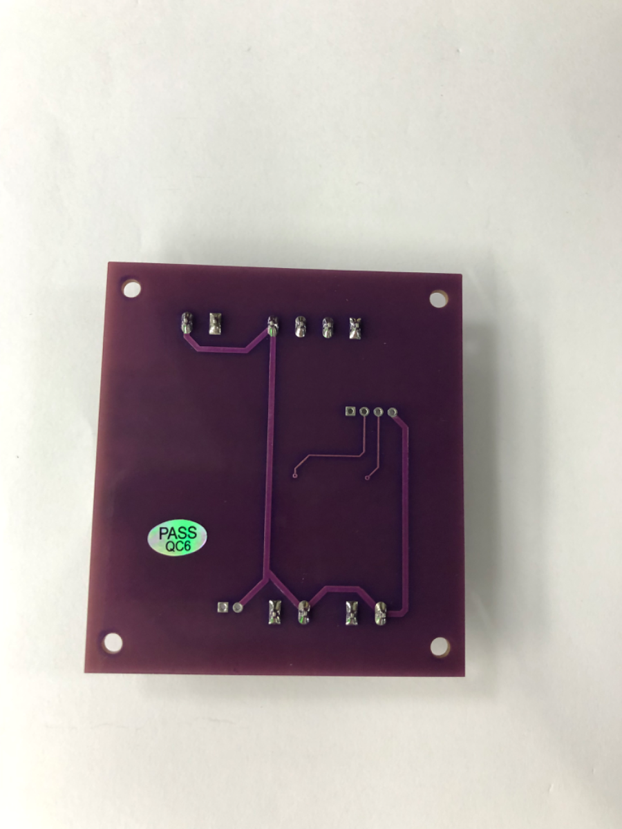
Files required to build your own Detector or make changes using KiCAD V8
- Cosmic Ray Muon Dectector V7 SCH
- Cosmic Ray Muon Dectector V7 PCB
- Cosmic Ray Muon Detector V7 Bill of Materials
File for Laser Cutting Base and 3D Print Connector Bracket
- Cosmic_Ray_Muon_Detector_V7_Base Plate Laser_Cut and Score
- 3D Print_Connector Brackets
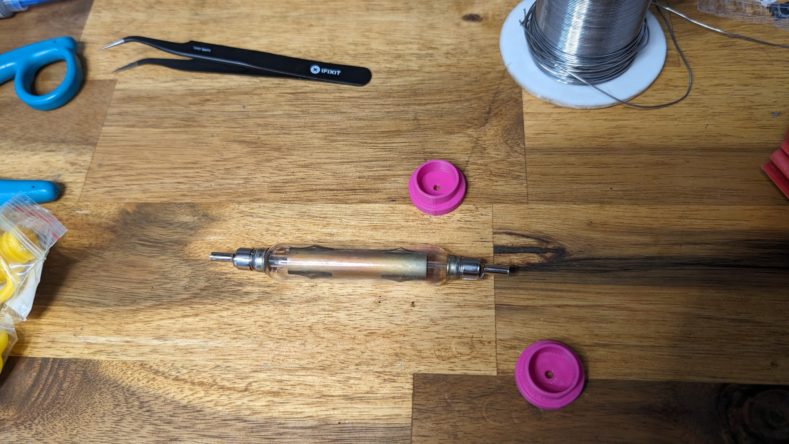
- 3D Print End Caps for 19.5 Dia. x 1.02 Copper Tube
Note: The above links are to .zip files so to download, right click and Save link as…
Contributors
A very big thank you to those who have be donated towards this project. Any financial contribution has gone directly towards this project. More importantly, I appreciated knowing others also appreciate this hobby.
Thank You!
- Simon – South Australia
- Anna – South Australia
- Lenticular Transmissions – US
PCB and Assembly Services
I recommend PCBWay for quality PCB manufacture or Elecrow for a complete turnkey assembly sollution at a low cost, excellent customer service and fast delivery.
Paul Schulz
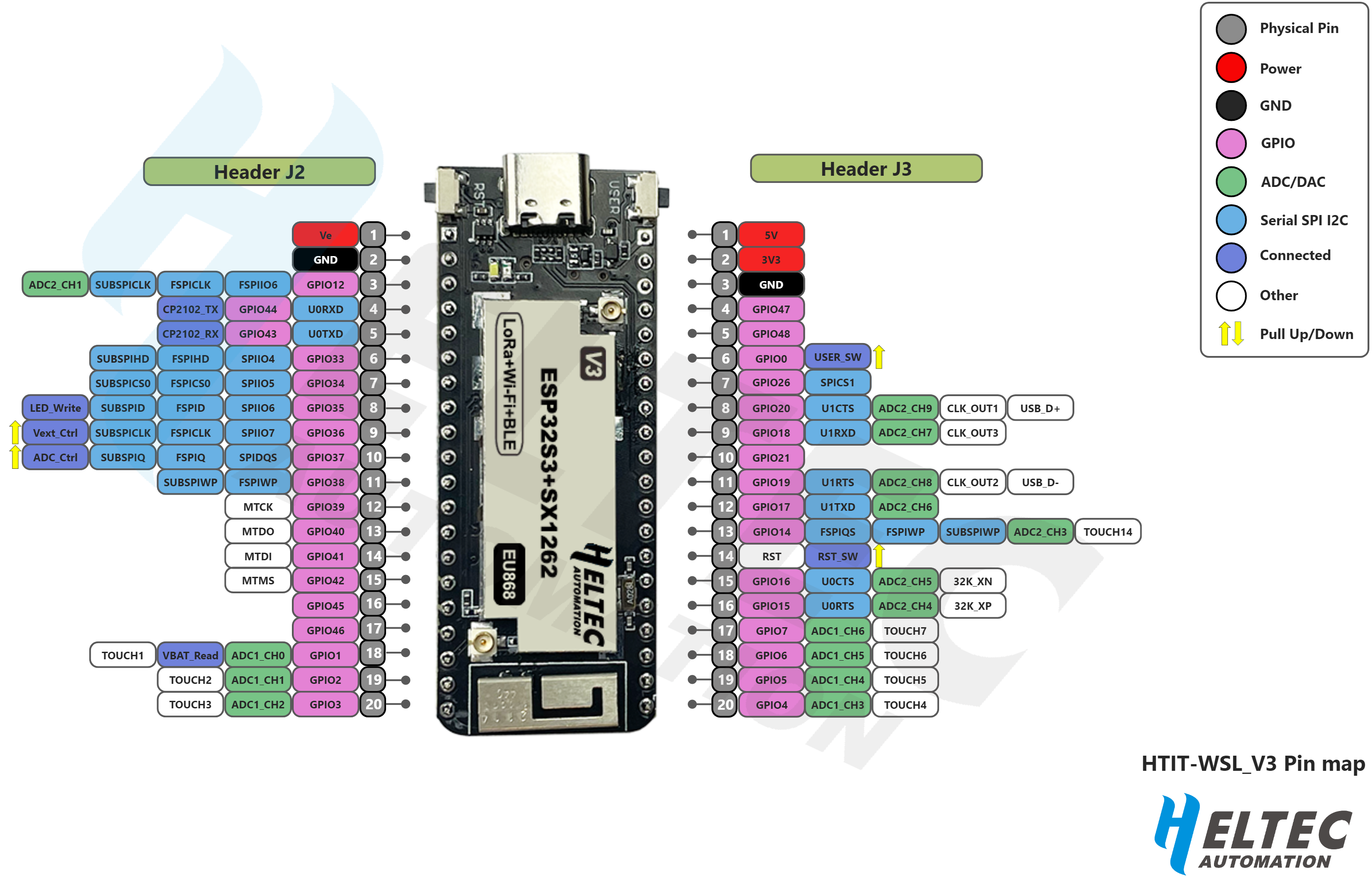
An amazing genuine person who has colaberated on many other projects with me. In this project he has developed code for the Wireless Stick Lite(V3) which includes Wireless and Bluetooth. This devices converts cosmic ray coincidance detections from the kit into data for analysis over wirelesss and also triggers a string of addressable LEDs. Code for this project is available on GitHub – PaulSchulz/hardhack-muon-detector: Code and Documentation for the Hardhack Muon Detector kit
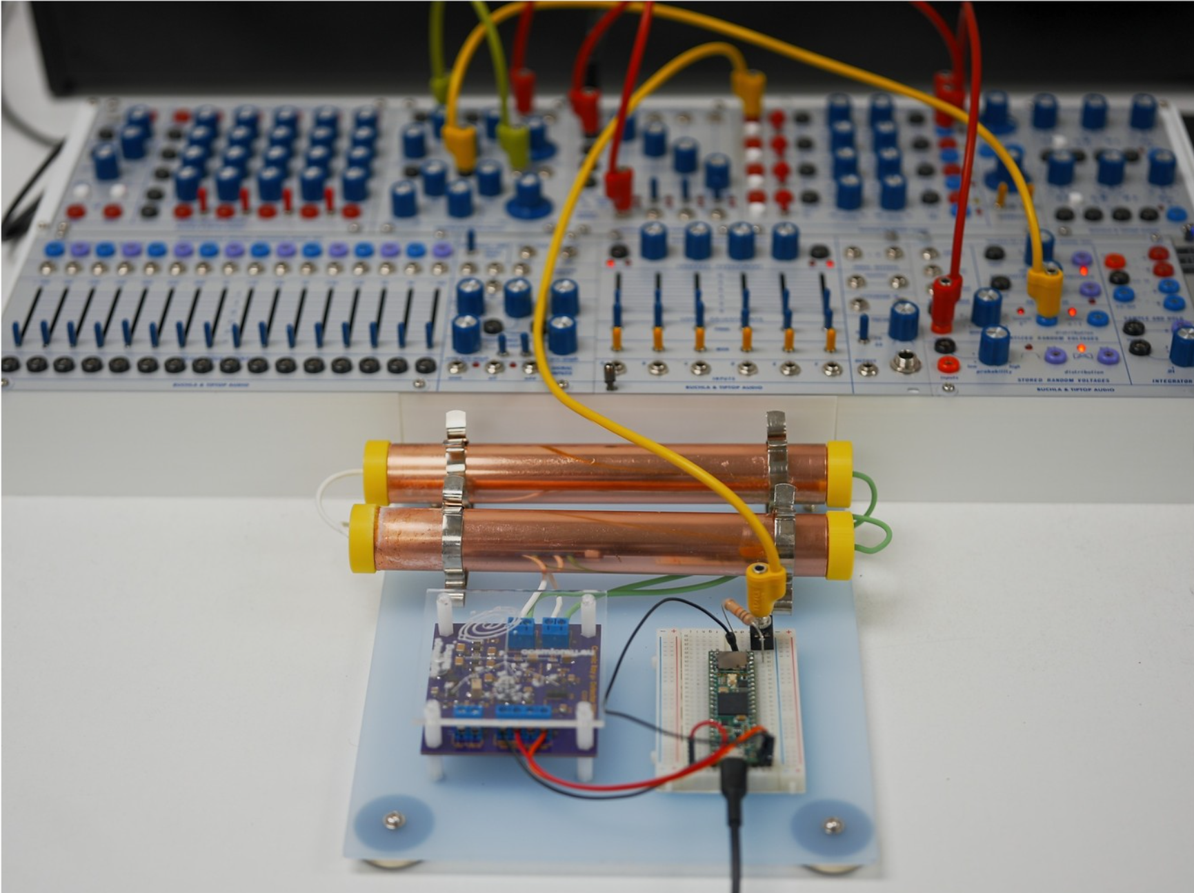
Musician Littelscale – Sebastian Tomczak
A Long-time supporter of my projects, has use this detector as a bus powered device to trigger tiptopaudiofficial Buchla modules (Synthesizer) via a #Teensy. The Teensy also outputs USB MIDI so that DAW events Sythersyser can be triggered by cosmic rays.
Darren Curtis South Australian artist-musician from Sacred Resonance.
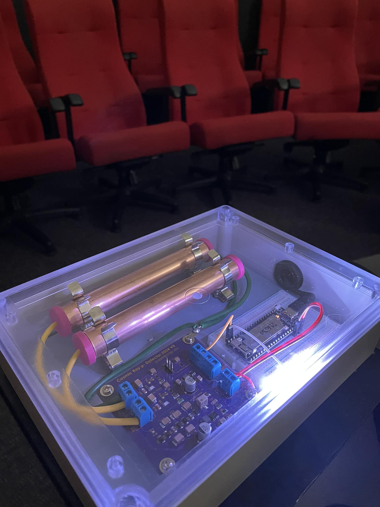
My initial financial contribution to this project comes from Darren Curtis, an individual with a keen interest in crafting music inspired by the rhythms of nature. Over the past 8 years, Darren has successfully incorporated some of my other detectors into his performances. In preparation for the 2024 Adelaide Fringe his group Sacred Resonance are using 3 of these kits. Each kit is enclosed in transparent box, featuring Paul’s Wireless Stick Lite (V3) boards and accompanying code designed to drive 10 addressable LEDs.
These units are interconnected over a Wi-Fi network, enabling the transmission of data. The information gathered by these detectors will play a crucial role in the creation of regenerative music, a artistic endeavor facilitated by Max, also known as Max/MSP/Jitter. Max is a visual programming language specifically tailored for music and multimedia, ensuring a auditory experience during this upcoming performance.

Help make this kit available to others
I’ve personally financed much of the prototyping expenses using my own resources. Should you wish to contribute financially, regardless of the amount, your support would be greatly appreciated. I want to let you know that this endeavour is not driven by commercial interests, as outlined earlier. For more extensive endorsements of this project, you will receive exclusive access to CAD files and Part Lists, securing your priority status when ordering a kit. Regardless of how modest, I want you to know that your help will bring this initiative to fruition.
Please follow this link to make a PayPal donation.
Photo Gallary